Parameter
Potential Technology
RVP, density, sulfur content, aromatics
RVP Analyzer, Vibrating Element Density Meter, Gas Chromatography (GC)
H₂ purity & flow
Thermal Conductivity Analyzer (TCD), Tunable Diode Laser Absorption Spectroscopy (TDLAS)
H₂, H₂S, light hydrocarbons
TDLAS for H₂S, Non-Dispersive Infrared (NDIR) Gas Analyzer, GC
H₂S removal efficiency, hydrocarbon composition
GC, TDLAS for H₂S
H₂, H₂S, CO, hydrocarbons
NDIR, TDLAS, GC
Residual sulfur, H₂ balance
GC, TDLAS for H₂S
O₂, CO, CO₂, NOx
Zirconia O₂ Analyzer, NDIR for CO/CO₂, Chemiluminescence for NOx
LPG composition, H₂S, moisture
GC, TDLAS for H₂S, Aluminum Oxide Moisture Analyzer
H₂, CO, CH₄, H₂S
NDIR, TDLAS, Catalytic Bead Detector (for combustibles)
Sulfur content, density, RVP
GC, Vibrating Element Density Meter, RVP Analyzer
Parameter
RVP, density, sulfur content, aromatics
Potential Technology
RVP Analyzer, Vibrating Element Density Meter, Gas Chromatography (GC)
Parameter
H₂ purity & flow
Potential Technology
Thermal Conductivity Analyzer (TCD), Tunable Diode Laser Absorption Spectroscopy (TDLAS)
Parameter
H₂, H₂S, light hydrocarbons
Potential Technology
TDLAS for H₂S, Non-Dispersive Infrared (NDIR) Gas Analyzer, GC
Parameter
H₂S removal efficiency, hydrocarbon composition
Potential Technology
GC, TDLAS for H₂S
Parameter
O₂, CO, CO₂, NOx
Potential Technology
Zirconia O₂ Analyzer, NDIR for CO/CO₂, Chemiluminescence for NOx
Parameter
LPG composition, H₂S, moisture
Potential Technology
GC, TDLAS for H₂S, Aluminum Oxide Moisture Analyzer
Parameter
H₂, CO, CH₄, H₂S
Potential Technology
NDIR, TDLAS, Catalytic Bead Detector (for combustibles)
Parameter
Sulfur content, density, RVP
Potential Technology
GC, Vibrating Element Density Meter, RVP Analyzer
Description
The FCC gasoline hydrotreater allows olefinic and cracked naphtha to be hydrodesulphurised to meet gasoline blending specifications. In order to produce products for gasoline blending, the unit’s secondary objectives are to minimise reductions in product RVP and octane.
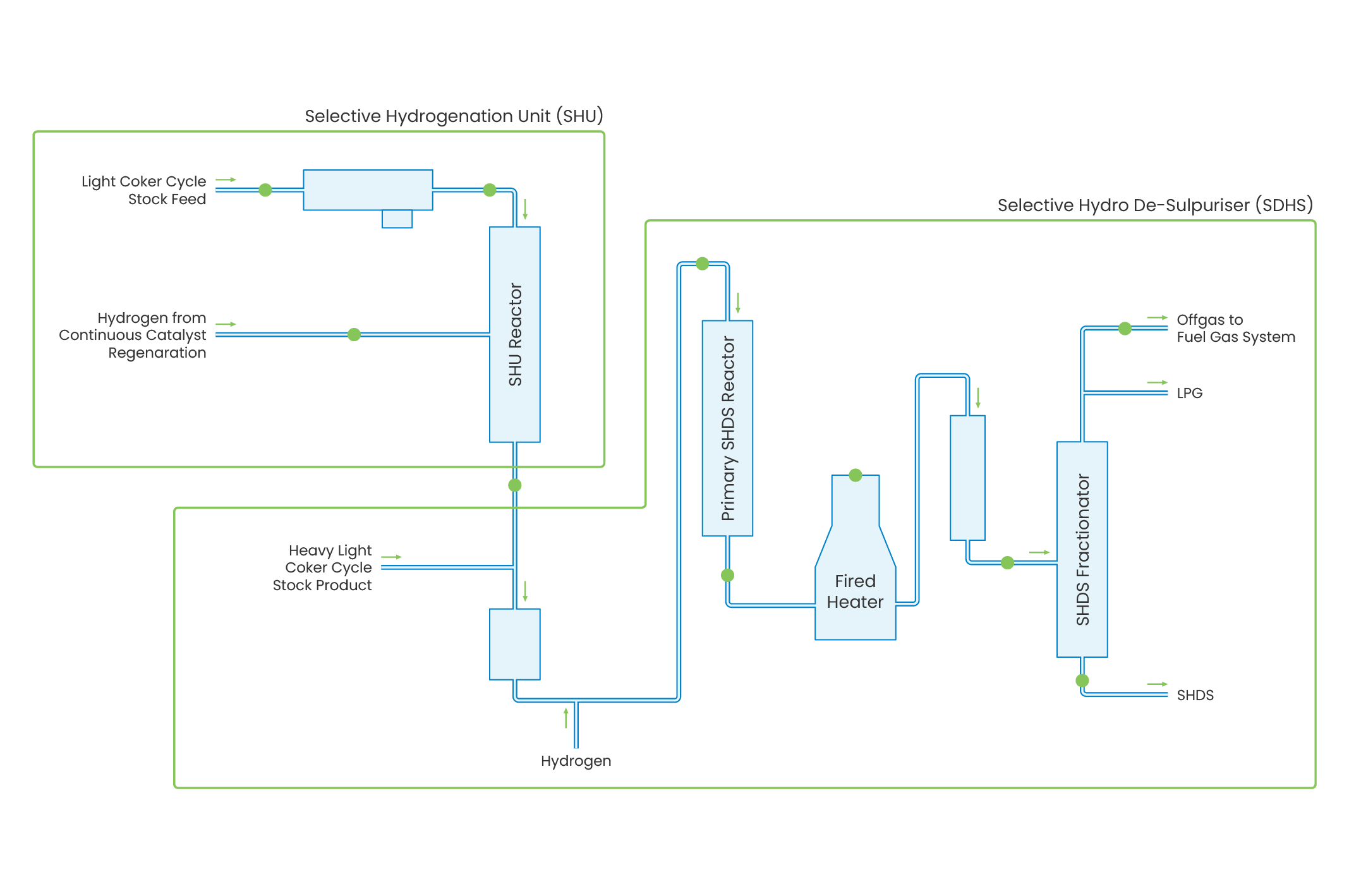
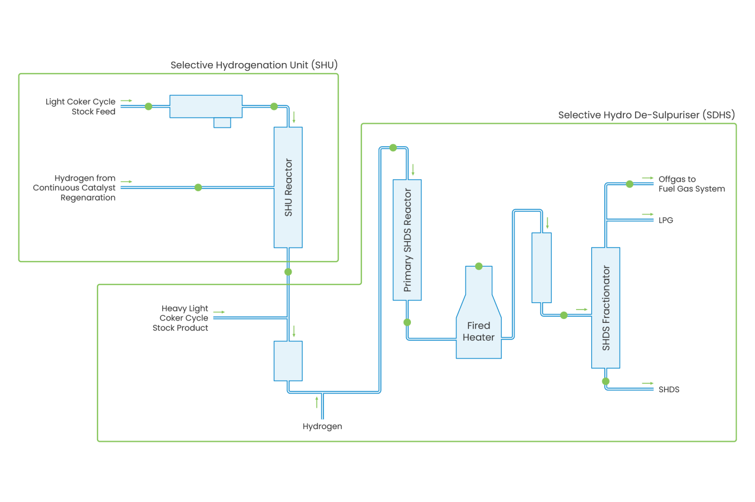
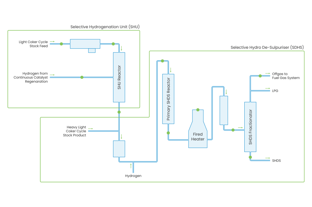
In order to minimise the octane loss across the process, the selective desulphurisation unit is often paired with a Selective Hydrogenation Unit (SHU) which contains a di-olefin saturation reactor to minimise the potential for polymerisation.
The SHU reactor product is separated by a naphtha splitter to allow olefin-rich light naphtha to be fed to the gasoline pool or to act as alkylation unit feed. The heavy cracked naphtha from the bottom of the splitter is mixed with additional hydrogen to undergo further desulphurisation. The final reactor catalyst targets mercaptan desulphurisation.
FCC Naphtha cannot be routed to the NHT there for multiple reasons, the key one is that olefins in cracked naphtha provide a large part of the octane when it is blended into gasoline. When hydrotreated (rather than selectively hydrotreated in a dedicated FCC naphtha treatment unit), these are saturated and there is a very large associated loss in octane number.